This is the first in what I expect to be an occasional series about 3D models and prints that I design. The code for this post, and some 3D models, are available in the associated github repo.
If you get into 3D printing, it's almost inevitable that you'll eventually print a vase. Vases are in a particular sweet spot-- they're sculptural, architectural, and potentially intricate, but with very few structural requirements. You can show off the precision of the printer and its flexibility without worrying that it has to hold a load, or withstand forces trying to break it at layer boundaries.


Vases fit the build area of most printers well--they exercise a lot of the Z-axis but their narrow footprint makes each layer relatively fast--a 6-hour print on draft settings instead of a 15 or even 20-hour print for a wider, tall part. And if you broaden the definition of "vase" to include objects that couldn't actually keep flowers in water, you can explore your printer's performance limits as well--how much of a bridge or overhang can you get away with? How small can you make a detail?
My latest vase was an exercise in tiling a simple shape. I took an octogon-based pattern that I found on Wikipedia, modified it for printability, and composed it into a tower structure. The result weighs in at a 64 lines of OpenSCAD, and I was pleased with how it printed. While I was designing it, I got some ideas for library functions, and now I'm back to harvest a few of them.

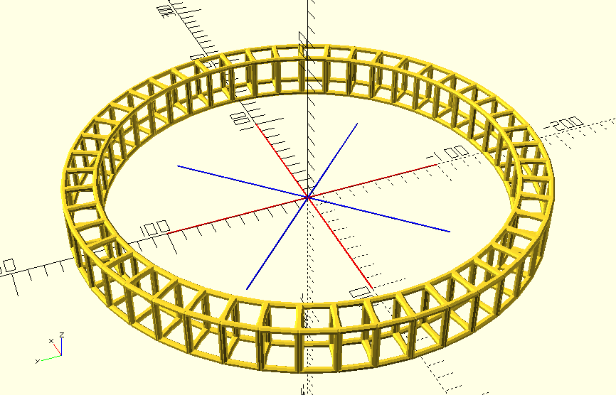
The figure above shows the basic building blocks of the vase. It starts with a bar, then a single figure, which is projected around an axis to form a ring. These rings are then repeated vertically to form a vase structure. In this case, each ring is tilted inward or outward, giving the final product an undulating profile. In each ring, the shape itself is alternated with its mirror image. Other modifications to the basic scheme are possible-- using two alternating shapes, stretching or compressing various aspects, even curving or distorting things. For now, though, I want to build a couple of basic functions that take a simple shape and tile it into a vase. I'll try to keep potential improvements in mind as I go, without getting too distracted trying to follow up on every idea. Start small, stay focused, work hard for a while, write up my notes, then rest. That's my optimal cycle.
I'll use a rectangle as my basic tile. The rectangle will stand in for the octogon from the last vase, or any shape I decide on later.

// FN controls how many faces the cylinders
// and circles have. I keep it to a low value
// during development to speed up render time.
FN=8;

// Default bar diameter.
DIA=4;

// This method of making a bar takes the convex hull
// of a pair of spheres centered at the specified points.
// I like this method better than using cylinders for two
// reasons. First, it's usually easier to just specify the
// beginning and end points of the line you want to draw than
// to work out the rotation and translation factors for
// a cylinder of the right length and diameter. Second, the
// spherical ends of a bar created this way are much better
// for connecting multiple bars together than the flat ends
// of a cylinder.
//
// @param a (Array) : [x, y, z]
// @param b (Array) : [x, y, z]
// @param dia (Number) : diameter
module bar(a, b, dia=DIA, $fn=FN) {
  hull() {
    translate(a) sphere(DIA / 2, $fn=$fn);
    translate(b) sphere(DIA / 2, $fn=$fn);
  }
}

module bar_rect(height, width) {
  bar([-width / 2, 0, 0], [width / 2, 0, 0]);
  bar([-width / 2, 0, height], [width / 2, 0, height]);
  bar([width / 2, 0, 0], [width / 2, 0, height]);
  bar([-width / 2, 0, 0], [-width / 2, 0, height]);
}

bar_rect(20, 10);
Next, I want to write a module that creates a ring of rectangles. What I want is a function like this:
module ring(side_width, num_sides) {
  for (side = [0:num_sides - 1]) {
    rotate[[0, 0, side * 360 / num_sides]) {
      translate([0, /* correct distance from center*/, 0]) {
        /* shape */;
      }
    }
  }
}
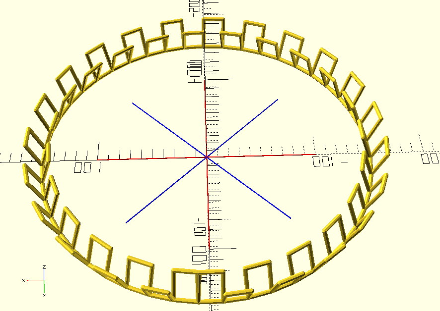
First, I need to figure out the distance each side should be from the center. The following figure shows four rectangles arranged around the origin. The module needs to figure out how far along the red lines to place the objects so that their edges meet, using only the number of objects and their base width. I can hear my 10th-grade geometry teacher laughing at me.

I know that the angle between the blue lines is 360 / num_sides,
which in this case means 90. I know that the angle between a blue
line and either of its red neighbors is half the angle between the
blue lines: 45, in this case. I want to place the rectangles at
the spot on the red lines where their corners land exactly on the
neighboring blue lines. So the distance between the red line at the
specified point and the neighboring blue line should be half of the
width of the base of the rectangle.

This is pretty nice. If I imagine that the blue line is a function of x, I know that its slope is the tangent of the angle at which it meets the x-axis. And if I know the slope, it's easy to find the point where the value of the function is half of the width--I just divide half the width by the slope.
angle_between_sides = 360 / num_sides;
angle_to_axis = angle_between_sides / 2;
distance_from_center =  tile_width / 2 / tan(angle_to_axis);

Now I can fill in one missing piece of my ring module:
module ring(side_width, num_sides) {
  angle_between_sides = 360 / num_sides;
  angle_to_axis = angle_between_sides / 2;
  distance_from_center = tile_width / 2 / tan(angle_to_axis);

  for (side = [0:num_sides - 1]) {
    rotate[[0, 0, side * 360 / num_sides]) {
      translate([0, distance_from_center, 0]) {
        /* shape */;
      }
    }
  }
}
Now there's an issue. OpenSCAD doesn't actually store models as variables; that is, the expression
my_cube = cube([10, 10, 10]);
is not valid. Another limitation is that modules aren't first-class
objects--they can't be passed as arguments to other modules. This
makes repeating a shape a bit inconvenient--if I can't pass the shape
as an argument to my ring module, and I can't pass the module that
defines it as an argument either, I need another way to access it
within the loop. Fortunately, there is a way to do this--it's just
not very obvious.
Many OpenSCAD functions like translate and rotate affect the
models that appear after them in a statement. The following two
expressions are equivalent:
translate([10, 10, 10]) sphere(4);

translate([10, 10, 10]) {
  sphere(4);
}
In this syntax, the sphere object is one of the children within
the translate block. I can use this same syntax within my module:
module ring(side_width, num_sides) {
  angle_between_sides = 360 / num_sides;
  angle_to_axis = angle_between_sides / 2;
  distance_from_center = tile_width / 2 / tan(angle_to_axis);

  for (side = [0:num_sides - 1]) {
    rotate[[0, 0, side * 360 / num_sides]) {
      translate([0, distance_from_center, 0]) {
        children(0);
      }
    }
  }
}
Now, if I want to make a ring with 47 sides, all tiled with the same rectangle, I can just use
ring(20, 47) bar_rect(30, 20);

I know I said that I was going to stay focused on a simple use case
and not get distracted trying to implement every cool feature I
could think of, but there's one simple change to this function that
will let me alternate tiles within the ring. The $children variable
automatically gets set to the total number of children in the block.
So if I just change children(0) to children(side % $children)
it will automatically repeat any number of children as it goes
through the ring.
ring(20, 47) {
  rotate([20, 0, 0]) bar_rect(30, 20);
  rotate([-20, 0, 0]) bar_rect(30, 20);
}
At this point you can see the possibility for some extraordinarily powerful abstractions. For instance, I should be able to make a ring of rings:
ring(20, 47) {
  ring(20, 4) bar_rect(30, 20);
}
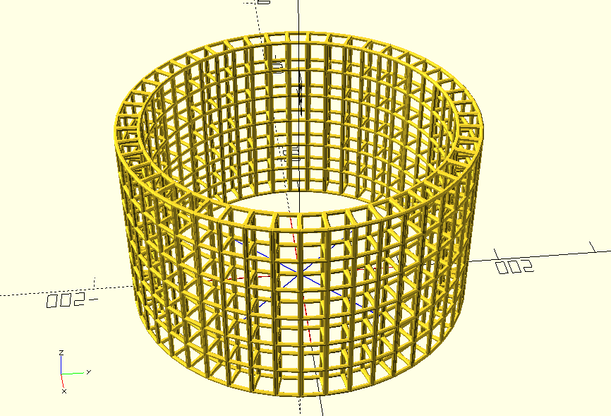
But this was about vases, which means that I still owe a module
for stacking rings to make a vase. All the building blocks of that
module are already included in the ring module. In fact, it would
be easy to add an outer loop in the ring module and an argument
to specify the number of levels. But I noticed that it was actually
more flexible to be able to specify a series of individual tiles,
so I think I'll also want the flexibility to specify individual
rings.
module stack(height, num_levels) {
  for (level = [0:num_levels - 1]) {
    translate([0, 0, level * height]) {
      children(level % $children);
    }
  }
}

stack(30, 6) ring(20, 47) {
  ring(20, 4) bar_rect(30, 20);
}
There are plenty of other ways to extend these ideas, but I'm going to leave them as an exercise for the reader. If you found this interesting, I strongly encourage you to download a copy of OpenSCAD and try it out for yourself. All the code is available in the github repo associated with this page.
In the 3d-printing community, it sometimes feels like OpenSCAD is the more "technical" modelling software, as opposed to more "artistic" software that's used for figure sculptures and the like. I think that OpenSCAD requires a lot of creativity, though. The thing I love about it is that it allows you to build a kind of fluency in the language of physical objects-- it helps you amass a personal vocabulary of little tricks and techniques that build on each other using the familiar software (and linguistic!) tools of abstraction and encapsulation. Learning to exactly specify and describe what you want allows you to compose your ideas into more and more complex structures not limited by your own attention span or manual skill. Don't get me wrong; I'm not saying this is better than any other way. Just that creative expression is a valuable thing, and sometimes the medium is code.