This is the second in an occasional series about 3D models and prints that I design. The code for this post, and some 3D models, are available in the associated github repo. The code for this post was largely inspired by the bending procedures posted to Thingiverse by the user flavius
In the [previous post]({{<ref "some_functions_for_vases.md">}}), I described how to use the children module in OpenSCAD
to repeat models in regular patterns--specifically, to make cylindrical tiled
vase sculptures. This post will explore what I call distortion fields--modules
that apply non-homogenous transformations to their children. A word of
warning: these techniques are extremely computationally expensive if you want
good results in many common cases. They also tend to require some massaging
to fit each specific case, so it's worth understanding how they work. The good
news is that with a few helper functions, distortion fields are fairly simple
to implement, so it's mostly a matter of coding for 10 minutes, pressing
"render," and going to get a beer.
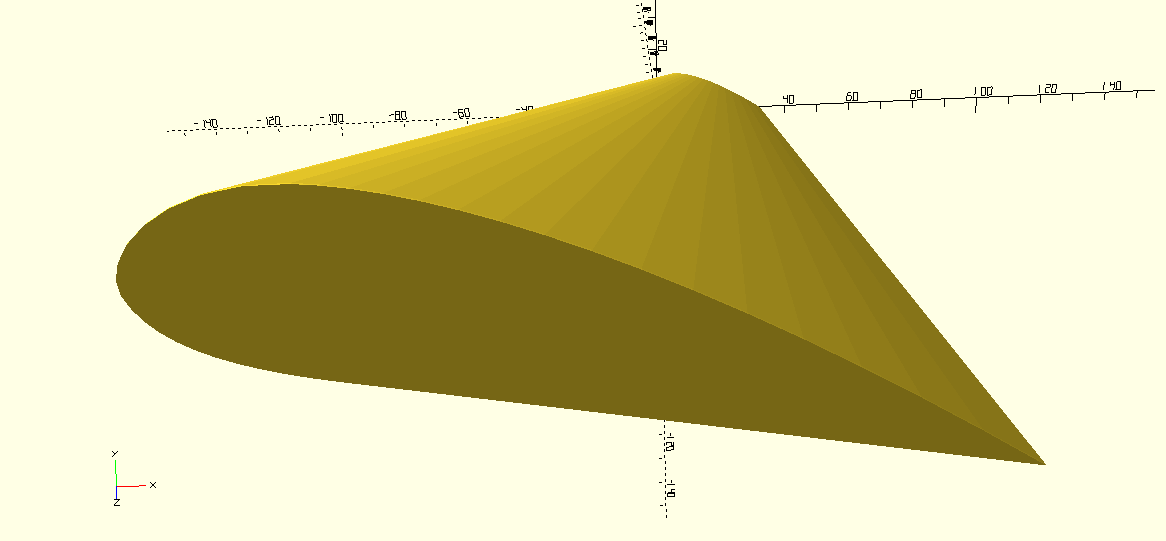
A good example of where a distortion field can be useful is in a model of an airplane wing (warning: I know nothing about actual aerodynamics). Wikipedia gives me a nice cross-section of an airfoil.

I'd like to take that cross-section and use linear_extrude to stretch it out
into a wing.
linear_extrude(height = 203) import("../dxf/airfoil.dxf");
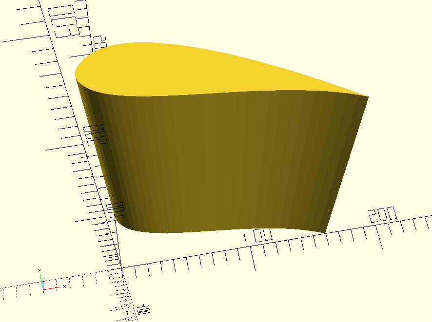
But that's not right. Wings are wider at their base, where they connect to the fuselage, and narrower at their tip. They're also usually more triangular, in top-down view, than rectangular. What I need to make this extruded airfoil into a wing is to apply a kind of "scale-gradient," so that it gets smaller from one end to the other, and also a "translation-gradient" so that it sweeps back from the big end to the small end.
The linear_extrude function does have a scale parameter, which will
help a little bit in this case.
module scaled_extruded_airfoil() {
  linear_extrude(height = 203, scale=[0.3, 0.3]) {
    import("../dxf/airfoil.dxf");
  }
}

scaled_extruded_airfoil();
This is good, but it doesn't give you a way to control where the end of the extruded
shape "lands." The leading edge of the wing is a straight line, based on some internal
representation of the origin of the 2D shape being extruded. I'd like the leading
edge of the wing to be swept back. Also, in many cases the model to be scaled will
be 3D, so this nice linear_extrude scaling trick won't be available. Or I might
want to scale an object in a way that is not linear along its length, and this
trick won't be suitable.
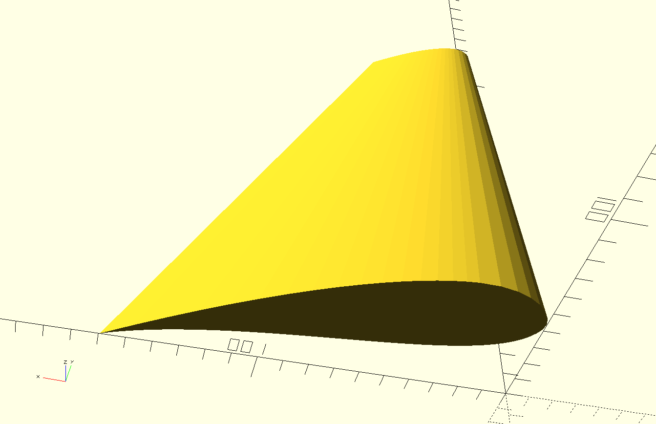
One way to try to achieve a "scaled and swept-back" effect is with a clever use
of hull to unite a big, thin airfoil cross-section with a smaller cross-section
translated one wing-length away. This is a good approach when it works, because
it is far cheaper, and the result far smoother, than using a distortion field, as we'll
see. But hull has its own price: it eliminates any concave details in the
model. Holes and indentations, like the scooped bottom of the airfoil, do not
survive.
module hull_wing() {
  hull() {
    linear_extrude(height = 0.5) {
      scale([0.2, 0.2, 1]) import("../dxf/airfoil.dxf");
    }
    translate([-100, 0, 203]) {
      linear_extrude(height = 0.5) import("../dxf/airfoil.dxf");
    }
  }
}

hull_wing();
As an introduction to how distortion fields work, let's look at how OpenSCAD models cylinders. If I make a simple cylinder, the result will be a prism with very obvious facets, not a smoothly-curved one.
cylinder(10, d-5);
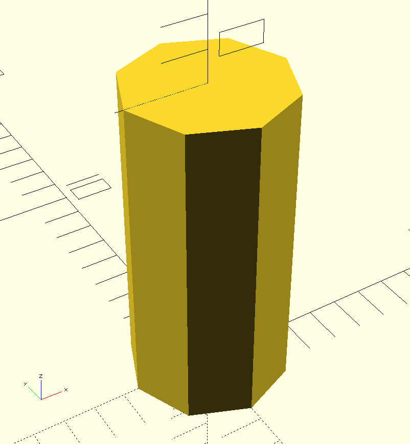
If I want a cylinder with a smooth surface, I can manually specify the
number of facets using the $fn parameter.
cylinder(10, d-5, $fn=30);

The best number of facets is the lowest number that still looks like a curve in the eventual object. I'm usually making models for 3D printing, and I know that when each facet is small enough, the printer is just going to print a smooth curve. The central idea is that small-enough details blend together.
To apply that idea to the wing model, I can imagine applying successive
transformations to arbitrarily-small slices of the wing, so that the
final result would be a relatively-smooth approximation of the shape I wanted.
I could make thin wing slices with successive calls to linear_extrude, but
for the sake of demonstration I'm going to pretend that I only have a 3D
model to work with, which is often the case in practice. I can take a short,
wide cylinder (really any shape that can surround the 2D wing shape) and
superimpose it on the wing.
module extruded_airfoil_cylinder_superimposed() {
  linear_extrude(height = 203) import("../dxf/airfoil.dxf");
  color("red") translate([100, 0, 0]) cylinder(1, d=300);
}

extruded_airfoil_cylinder_superimposed();
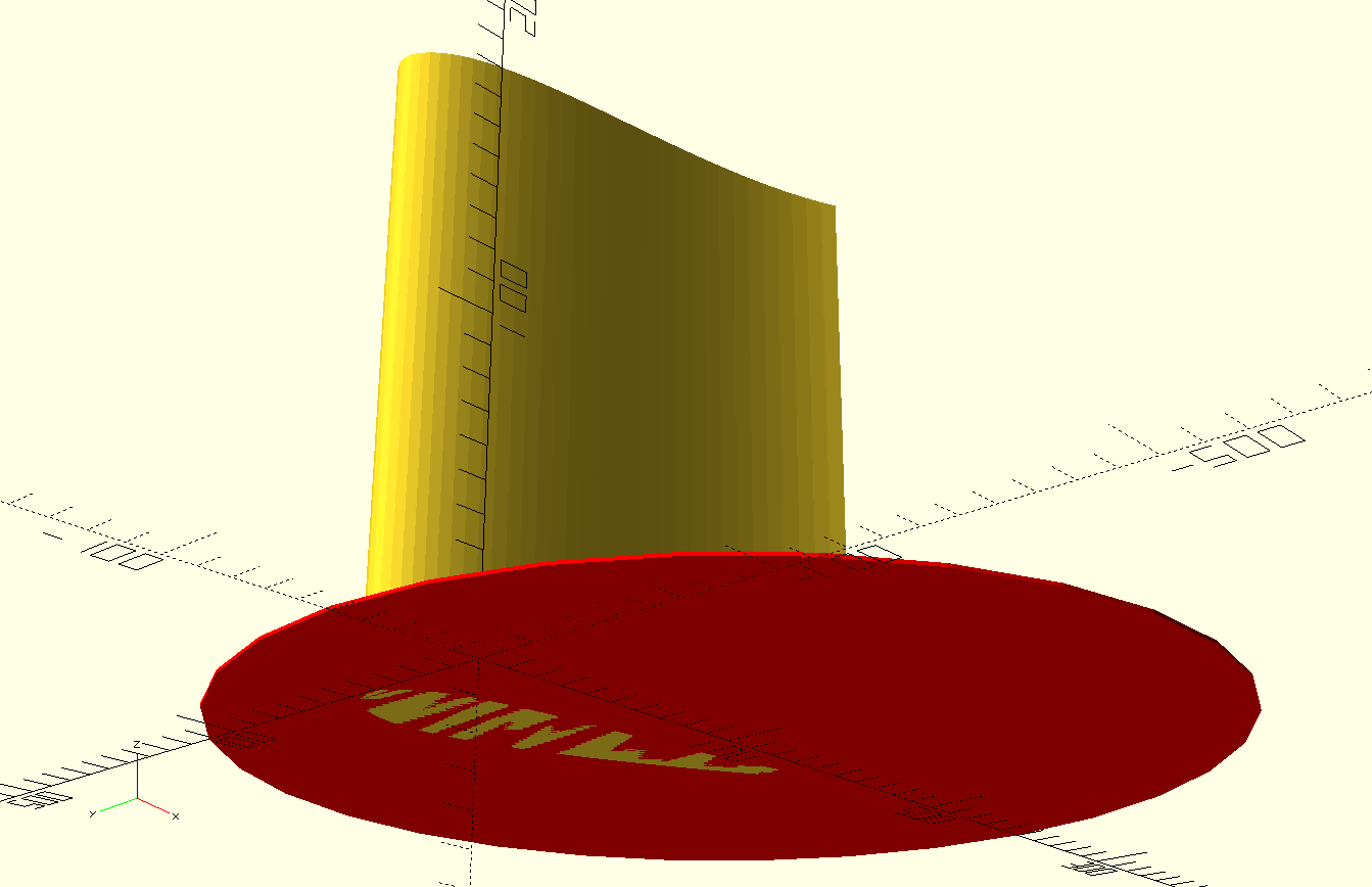
Now, if I take the intersection of these shapes, I should be left with a slice of the wing that has the same (thin) height as the red cylinder.
module intersection_airfoil_cylinder() {
  intersection() {
    linear_extrude(height = 203) import("../dxf/airfoil.dxf");
    color("red") translate([100, 0, 0]) cylinder(1, d=300);
  }
}

intersection_airfoil_cylinder();
There's a special kind of tipping point I always look for in any technical project. It's the point where I've figured out, not exactly how to do the thing I want, but enough to know that it can be done. Sometimes the process of getting to that tipping point is called "driving out risk," with the idea that once you hit it, there are no more risks that have the potential to fundamentally prevent what you want to do. After I know that I have all the building blocks to realize my idea, my next step is to get a working version, no matter mow ugly. Once I have a working version I can refine it as necessary (but it's surprising how often an initial version works for all the cases that matter!).
At this point I have all the building blocks I need to make the wing.
- I can make a thin slice of an object if I know its approximate dimensions in X and Y.
- I can scale and translate a thin slice of an object.
- I can use the
childrenmodule to refer to an object to be distorted.
In pseudocode, the algorithm I want to implement looks like:
// This isn't real code!
// start and end are [x, y, z] vectors for the translation.
module translate_field(diameter, height, steps, start, end) {
  for (i=[0:steps - 1]) {
    // take the intersection of the transformed object and
    // a cylinder to cut out a thin slice
    intersection() {
      // apply the appropriate transformation to the object.
      // note that the interpolate function doesn't
      //exist in OpenSCAD, I need to write it myself
      translate(interpolate(start, end, steps, step)) {
         children(0);
      }
      // translate a thin cylinder to the correct height for this
      // step on the original object
      translate([0, 0, i * (height / steps)]) {
        cylinder((height / steps), d=diameter);
      }
    }
  }
}
Functions in OpenSCAD have a kind of odd syntax. I haven't looked
into it in depth, but when I need to write one I often refer to
the documentation.
Suffice it to say that the interpolate function can be implemented
this way:
function interp(start, end, steps, step) =
  let (pct = step / steps)
  [
   start[0] + (pct * (end[0] - start[0])),
   start[1] + (pct * (end[1] - start[1])),
   start[2] + (pct * (end[2] - start[2])),
  ];
This is a good linear interpolation function, but I actually don't want to permit translation in the Z-axis, so I can write a helper function that prevents it.
function xy_interp(start, end, steps, step) =
  interp([start[0], start[1], 0], [end[0], end[1], 0], steps, step);
Now I should be able to use this function to complete the translate_field
function and use it to modify the scaled extruded airfoil.
// start and end are [x, y, z] vectors for the translation.
module translate_field(diameter, height, steps, start, end) {
for (i=[0:steps - 1]) {
// take the intersection of the transformed object and
// a cylinder to cut out a thin slice
intersection() {
// apply the appropriate transformation to the object.
// note that the interpolate function doesn't
//exist in OpenSCAD, I need to write it myself
translate(xy_interp(start, end, steps, i)) {
children(0);
}
// translate a thin cylinder to the correct height for this
// step on the original object
translate([0, 0, i * (height / steps)]) {
cylinder((height / steps), d=diameter);
}
}
}
}
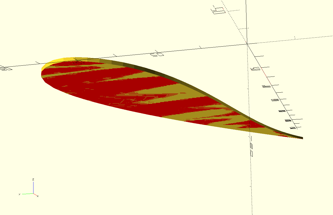
module scaled_translated_wing(steps) {
translate_field(600, 203, steps, [0, 0, 0], [100, 0, 0]) {
scaled_extruded_airfoil();
}
}
translate([-200, 0, 0]) scaled_translated_wing(20);
scaled_translated_wing(50);
translate([200, 0, 0]) scaled_translated_wing(500);
{{
As the figure shows, it's possible to approximate a smooth distortion if I'm willing to pay a significant price in rendering time. As I said before, this can be an expensive technique, but its flexibility, and the fact that it can be applied to arbitary 3D shapes sometimes make it the best tool for the job.
Note that a big factor that affects rendering time is the number of parts that a model has. Each step consists of about three parts for rendering purposes:
- the whole wing, translated;
- the cylinder that intersects it
- the intersection of the wing and the cylinder
That means that for 500 steps, OpenSCAD is rendering 1500 objects. This is
why it's often better to construct a custom distortion field procedure
rather than "stacking" a set of generic ones. For instance, if I wrote a
scale_field module that did a linear scaling of an object the same
way the translate_field does a translation, and I had an object that I
wanted to both scale and translate, I could use the following code
module scaled_translated_wing(steps) {
  translate_field(600, 203, steps, [0, 0, 0], [100, 0, 0]) {
    scale_field(600, 203, steps, [1, 1, 1], [0.4, 0.4, 1]) {
      extruded_airfoil();
    }
  }
}

scaled_translated_wing(500);
But this would be a Bad Idea, because first the scale_field would
take the wing and generate 1500 parts from it, and then the translate_field
would do the same, for a total of 3000 parts. In a moderately complicated
model, where an object like this wing might be repeated a few times, the
rendering time would quickly become infeasible. Instead, it would be better
to write a custom scale_and_translate field that would apply both
transformations in a single pass.
Obviously, this technique is only a tool for situations where OpenSCAD doesn't have a better option built in. But in those situations it provides unparallelled flexibility. It's especially useful when you want to define a custom interpolation function. With a quadratic interpolation you can achieve a curved scaling or translation effect, which is often useful when you want a seamless transition between individual pieces that are meant to be screwed or glued together. It's also nice to have the ability to apply these kinds of effects after you have designed the individual parts, so that the design of the part itself isn't burdened with the detail of how it attaches to the rest of the system.
All the code for this post is available in the associated github repo. If you liked it, I encourage you to download a copy of OpenSCAD and try it out for yourself.